


All CNC parts begin with a design choice. The design of a component can have an impact on its manufacturing time, manufacturing costs, and inspection results. However, in most production scenarios, design and manufacturing have not been integrated until issues arise on the shop floor.
Bad design adds up. It is an unnecessarily tight tolerance, an awkward internal geometry, and then, suddenly, a simple part calls for three setups, special tooling, and a longer cycle time. The consequence: higher rejections, longer lead times, and higher costs.
Design for Manufacturability (DFM) directly tackles this. In CNC manufacturing, it translates to designing parts that are functional and feasible to manufacture while still achieving the required performance and functionality. It is a guide to the principles that all engineers and product designers need to be familiar with before they send a CNC part drawing off to production.
What is Design for CNC Machining?

Design for CNC machining is the design of a part from the beginning, with the manufacturing process in mind. It fills the gap between the requirement of functionality in a design and the efficient ability of a CNC machine to produce that design.
CNC machining is a subtractive manufacturing process. Material is cut with rotating cutting tools controlled by a programmed tool path. That physical reality creates rigid limitations: tools can only be so long and so thin. They can’t cut around corners, and thin structures will bend under cutting forces. A design that doesn’t account for these factors exposes machinists to cost, risk, and variability.
DFM is a perfect match between design goals and machining capability. It is not about simplifying the design but about making it possible to perform the desired function with a geometry that can be reliably, quickly, and economically manufactured on a CNC machine.
Why CNC Design Guidelines Are Important in Production.

By consistently applying these CNC machining design guidelines, the production benefits can be measured:
Less machining time: Simplified geometry translates into shorter, more efficient tool paths and fewer operations.
Reduced tooling costs: Being designed for standard cutter sizes means no need to buy special tools.
Better dimensional accuracy: Designing to accommodate the capabilities of the machines makes it easier to maintain dimensional accuracy over the long haul.
Faster lead times: Parts which need fewer setups and easier fixturing get through the shop quicker.
High repeatability: Constant stable geometry with high machinability.
Multiplication happens when it’s high-volume production. The two-minute-per-part design change equals 2,000 minutes for a 1,000-piece order. That is real money.
The Selection of Materials and Their Impact on CNC Design.

The selection of materials affects all aspects of CNC manufacturing. It affects tool selection, tolerances that can be obtained, surface finish, and cutting speed. The wrong material in the wrong application leads to a failure in performance of the part or to an undue amount of machining difficulty.
Aluminum alloys
The most common metals used in CNC work are aluminium alloys, such as 6061 and 7075. They can be machined rapidly, with excellent surface finishes and without undue tool wear while keeping tolerances close. If care is taken with fixturing, thin walls and fine features can be made.
Stainless steel
Stainless steel is corrosion resistant and strong, but slow to machine. Hardening grades such as 304 will be especially tough on tooling. Parts should be designed to have a generous wall thickness and features that would require a long dwell time.
Tool steels (D2, H13, P20)
Depending on the application, tool steels (D2, H13, and P20) are machined in a pre-hardened or soft condition. Hard milling causes deflection concerns; designing parts with thin features in hardened material or designing to tight tolerances should be accomplished through grinding or EDM.
Engineering plastics
Clamping forces and thermal effects should be taken into account for engineering plastics (Delrin, PEEK, nylon). They are easily and rapidly machined but may be distorted when the wall thickness is too thin, or when stresses are caused during the machining.
The adage is to match the material to the functional requirement and then design the geometry to the machining characteristics of the material.
Essential CNC Machining Design Principles

These guidelines are for the most frequently encountered causes of machining difficulty and cost in designing CNC parts.
Internal Corner Radii
CNC end mills have a round shape. Conventional corners must be square, which is hard to achieve with EDM or broaching. Indicate a corner radius of at least 130% of the cutting tool radius (for a 10mm cutter, 6.5mm or greater). The larger the radii, the larger and more rigid the tools will be, minimizing deflection and resulting in more accurate cutting.
Wall Thickness
For metals, maintain walls of 0.8 mm minimum; 1.5 mm or more is desired for structural features. Thin walls bend and cause inaccurate dimensions and poor surface finish when cut. When it comes to plastics, always remember to keep the minimum at 1.5mm to avoid clamping distortion.
The measurement of the depth of a hole and the diameter of the hole.
Standard drills and reamers reliably operate to a depth of 3 times the diameter. Peck drilling cycles, specialized tooling, and slower feed rates will be needed for deep holes (6x diameter or deeper). Make holes with a depth-to-diameter ratio of 4:1 as much as possible. It is not so much of an issue for through-holes.
Thread Design
Indicate standard thread forms for common thread sizes (M3, M4, M5, M6, M8, M10, or imperial UNC/UNF). Left-hand and non-standard pitches increase cost. The maximum depth of the thread is 1.5 times the nominal diameter; a deeper thread means more risk of tap failure.
Unneeded tight tolerances.
Not all dimensions require the same tolerance. A smaller tolerance may be ± 0.01 mm or less, which will need a slower feed rate, extra inspection processes and may need a dedicated grinding or honing process. Use tight tolerances only when the function requires it, such as bores, bearing seats, locating features, and standard tolerances in all other places (+/- 0.1mm to +/- 0.05mm).
The conventional tool size optimisation method.
The standard tool size optimisation method.
Design pockets, slots and profiles to size that matches standard cutting tool sizes. This 12mm-wide slot was cut efficiently with a 12mm end mill. A 13.3mm slot will need a special tool or a sub-optimal multi-pass approach. Use reference standard tool catalogues for sizing features.
Understanding CNC Tolerances and Surface Finish
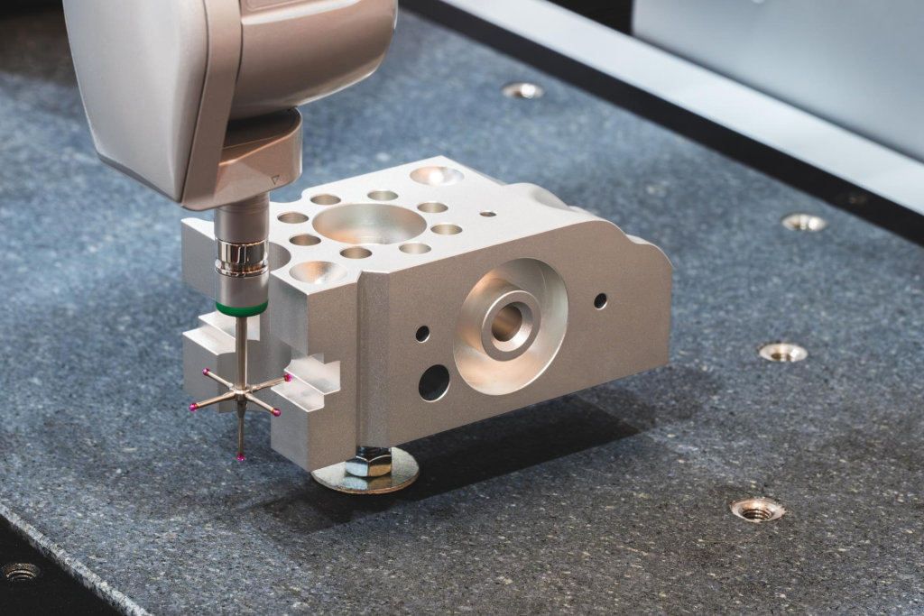
The design process directly translates to production costs in tolerance specification.
- The standard tolerance for CNC parts is within ±0.05mm to ±0.1mm without special efforts. Operations that are turned regularly can do so to a degree of ±0.025mm. Close tolerances of ±0.01mm or below will normally need to be ground, honed, or lapped, all of which are different processes and will involve an additional process cost and lead time.
- The same applies to surface finish. A standard 2.5 µm (63 µin) finish can be achieved at Ra 1.6 µm (63 µin). Fine parameters are required to finish Ra 0.8 µm. Generally, Ra of 0.4 µm or less requires post-machining processes such as polishing or lapping.
- Understand differences between functional and cosmetic finishes. The requirements for the Ra of a bearing bore with regard to the performance of the lubrication film. A non-contact face is one that looks good. The more surfaces that are treated, the higher the cost, but not the part performance.
Design Optimisation Strategies for Faster CNC Production

Design Optimisation is not at the expense of design intent. It involves providing the same functional result using fewer resources.
Reduce part complexity: Eliminate features that are not necessary for structural and functional aspects. Machining unnecessary decorative chamfers, boss patterns, and cosmetic contours consumes time without adding value to the part.
Minimize part setups: Each time a part is moved in the machine, there is potential for datum shift and further fixturing. Combine features to be machine oriented in as few orientations as possible. Four setups to perform a part are much more expensive than two setups.
Design for standard tools: dimension slots, pockets, and radii for tools available in existing tooling inventory. It completely cuts down on special tooling time and maintains constant unit costs.
FAQs
What are the key design rules to ensure parts are easy and cost-effective to CNC machine?
Apply internal corner radii of at least 130% of the cutter radius; Consider minimum wall thickness to be greater than 1.5mm for metals. Size features to standard tool size; Use tight tolerances only if function requires them; reduce the the number of machining setups.
What should be the minimum wall thickness, hole diameters, and feature sizes in CNC-machined parts?
For metals, use a minimum thickness of 0.8mm (preferably 1.5mm). Do not exceed 4:1 depth to diameter with standard tooling. Make holes of standard drill-hole size as far as possible; do not make a slot or pocket narrower than the smallest reliable cutter for that material.
What tolerances and surface finishes are feasible for typical CNC processes?
Without special effort, the standard CNC milling can be done with a precision of within 0.05–0.1 mm. Turning can be routinely done to a tolerance of ±0.025mm. Less than ±0.01mm should be ground or honed. A standard surface finish machined is Ra 1.6 µm, which is adequate for surface finish; a surface finish of Ra 0.4 µm or less will require post-machining operations.
What is the best way to achieve the part’s geometry to minimise setup, tool change, and machining time?
Design features that can be accessed from one or two setups, consistent pocket depths and radii throughout the part to minimize tool changes, and size features to suit standard tool inventories, and avoid cosmetic geometry that offers operations but no additional value in improving the part function.
Conclusion
CNC machining is an efficient, accurate, and flexible manufacturing technique. It is only when parts to be manufactured are designed to work with it, not against it, that its full potential is realized.
Good CNC part design is not about restricting creativity. It’s about engineering judgment to do the job at the lowest manufacturing cost necessary for the function while meeting the demands of reliability and production repeatability.
The best way to do this is to get your machining partner’s input early on. From precision aluminium housings to stainless steel surgical parts, working with an experienced CNC machining supplier can make you tension-free for all steps.


